Cold-formed steel (CFS) continues to shape the design of modern brick veneer wall systems.
Recent updates to the Brick Industry Association’s Technical Note 28B reflect expanded research, enhanced drainage wall strategies and improved material performance.
These revisions offer designers greater latitude with CFS deflection and reorganize the document with updated terminology and separate material and detailing sections.
A recent STRUCTURE Magazine article discusses the Tech Note 28B update. “Updated Design Recommendations for Brick Veneer on Cold-Formed Steel Framing,” by Cortney Fried, managing senior engineer at the Brick Industry Association, offers improved guidance for brick veneer assemblies backed by cold-formed steel.
Technical Note 28B addresses considerations and recommendations for the design, detailing, material selection and construction of brick veneer/cold-formed steel framed walls.
DOWNLOAD THE TECHNICAL NOTE 28B
Early Performance of Veneer Systems
Anchored brick veneer on a cold-formed steel backing became an option for exterior wall assemblies starting in 1968.
“The early assemblies were generally similar to the modern version,” says Fried. “They contained a single wythe of brick (nominally 3 or 4 inches thick) mechanically attached to a cold-formed steel framed backing with metal veneer ties spanning a prescribed cavity.”
The assemblies offered fast enclosure and reduced weight but often showed inconsistent stiffness and detailing. Early issues included cracking, spalling, water intrusion and tie problems.
To manage risk, earlier guidance adopted strict deflection limits for CFS framing. Those limits addressed real problems but did not reflect modern materials or today’s stronger CFS engineering standards.
The updated Technical Note 28B responds to decades of improved structural practice within the CFS industry.

The Trade Milwaukee exterior walls feature cold-formed steel (CFS) studs backing up brick and metal panels. The structural design has handled by Steel Framing Industry Association (SFIA) member raSmith.
Expanded CFS Deflection Options
BIA Technical Note 28B broadens acceptable deflection limits for CFS backings.
“The conservative recommendation of L/600 was intended to compensate for the lack of available research on the wall assembly,” says Fried.
Recent research supports deflection values between L/360 and L/600 based on project needs. This range better matches the stiffness, load paths and service conditions of today’s cold-formed steel assemblies.
“The changes in the BIA Technical Note 28B are not meant to supersede the existing L/600 deflection limit, but to expand the deflection limit options for designers,” says Fried. “Deflections between L/360 and L/600 can be used, as appropriate for the project.”
The update preserves the conservative option but offers designers flexibility for well-detailed projects. This shift moves from a single limit to a performance-driven approach rooted in CFS behavior. It helps designers balance serviceability, reliability and cost while meeting project expectations.
The expanded range also aligns with historical performance in other building codes.
Improved Cold-Formed Steel Organization
Technical Note 28B improves usability by reorganizing key guidance for cold-formed steel (CFS) backed veneer systems, providing clearer direction through the following updates:
- Separates material guidance from detailing guidance for clearer CFS wall design
- Identifies mandatory requirements and distinguishes them from recommendations
- Aligns terminology with current CFS industry standards
- Removes redundant content and improves overall navigation
- Supports consistent detailing across drawings, specifications, and fabrication documents
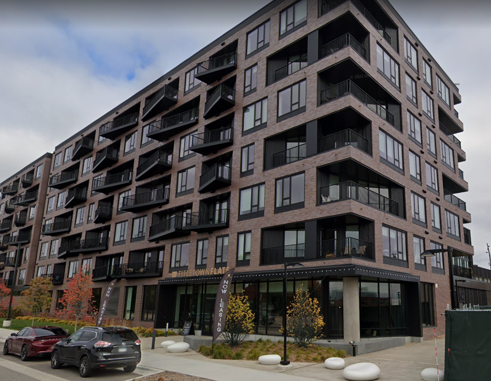
In this multifamily residential project in Green Bay, Wisconsin, custom cold-formed steel (CFS) beams support both the brick façade and the cantilevered balconies, preserving the clean exterior design.
Requirements for Cavities, Insulation and Corrosion
The updated technical note responds to wider cavity needs driven by modern energy codes. It includes larger tie sizes for cavities up to 6-5/8 inches, improving performance in CFS-backed walls.
“The increase in cavity width allowed for the inclusion of additional continuous insulation to meet the requirements of the energy code,” says Fried.
These changes help designers maintain insulation continuity without compromising structural reliability.
Flashing guidance is simplified to support common drainage wall construction. New details show stand-off shelf angles that protect thermal layers at the support point.
The note also adjusts minimum galvanizing from G90 to G60 for typical CFS applications. G90 remains suitable in coastal zones, humid interiors and other high-risk environments.
Guidance for parapets emphasizes continuous air, vapor, and insulation protection around CFS framing. The document refers to AISI S240 for cold-formed steel design and AWS D1.3 for welding.
Cold-Formed Steel’s Evolving Role
Cold-formed steel framing continues to lead exterior wall design due to its precision, strength and predictable behavior. The updated BIA Technical Note 28B reinforces this advantage by aligning veneer guidance with modern CFS engineering practice.
With expanded deflection options, clearer organization and refined detailing, the update offers designers stronger tools to create durable, efficient and reliable wall systems.
“It is hoped that this updated version of BIA Technical Note 28B will continue to serve as a useful resource to designers,” says Fried.
Read the full article from STRUCTURE Magazine.
Additional Resources
- Framing Excellence: The Trade Milwaukee Showcases raSmith’s Cold-Formed Steel Design Ingenuity
- Understanding the Layers of a Complete Wall System
- Using Brick Veneer and Metal Studs for Strong Walls