
How high can engineers build with cold-formed steel (CFS) framing? Seven- and eight-story buildings already demonstrate its capabilities in load-bearing construction. And now, a landmark seismic research project just completed offers evidence that could help engineers push those limits further.
What do engineers need to know about building tall, load-bearing structures with cold-formed steel? Building taller involves more than increasing structural capacity. Engineers must address gravity loads, lateral forces, floor systems, fire resistance and construction logistics.
Recent projects illustrate how design teams can tackle these challenges.
- The 7-story West Point II Apartments in Tucson, Arizona, substituted built-up CFS stud packs for structural steel components, saving more than $1 million
- The design of the 8-story Element Hotel in Richmond, Virginia, combined load-bearing CFS walls, floor joists and structural steel into a precise, repeatable framing system
- Researchers subjected a 100-foot-tall, 10-story CFS building to 18 earthquake simulations, which delivered data demonstrating the building’s resilience.
Together, these 3 projects reveal five engineering decisions that can shape the success of taller CFS buildings.
1. Design an Efficient Load Path
Tall CFS buildings require engineers to manage increasing gravity loads across successive floors. Wall placement, structural connections and floor systems determine how those loads reach the foundation.
Vertically aligned bearing walls offer one approach. By stacking CFS bearing walls, engineers can reduce the need for heavy structural transfer systems.
Specialty engineer Industrialized Construction Solutions used this strategy at West Point II Apartments in Tucson.
The original design called for 5 stories of wood atop a 2‑story concrete podium. But a feasibility analysis showed such a design would strain the project budget.
“The project team instead designed a full cold-formed steel superstructure,” says the BuildSteel™ case study. The project earned a Steel Framing Industry Association (SFIA) Efficient Use of CFS Framing Award.
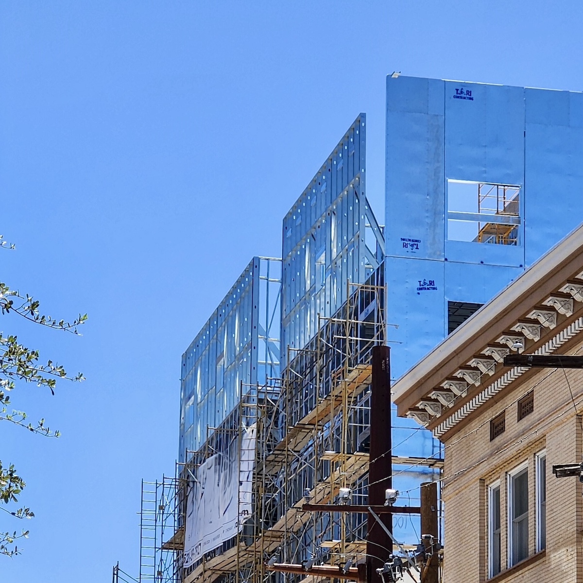
The 7-story West Point II Apartments uses vertically aligned cold-formed steel (CFS) bearing walls. The design eliminated concrete and structural steel transfer systems. Photo courtesy of Industrialized Construction Solutions
Engineers aligned load-bearing CFS walls from the upper residential floors through the first-floor amenities to the foundations. Two design decisions proved especially important:
- Aligned CFS bearing walls: Eliminated concrete and structural steel transfer systems
- Built-up CFS stud packs: Replaced HSS for shear wall hold-downs and balcony supports, saving more than $1 million
The project still required some conventional structural steel. Engineers incorporated limited wide-flange moment frames around large first-floor storefront openings.
West Point II demonstrates how early structural planning can improve a project’s financial feasibility. Coordinating bearing walls and load paths can eliminate costly transfer systems while maintaining structural performance.
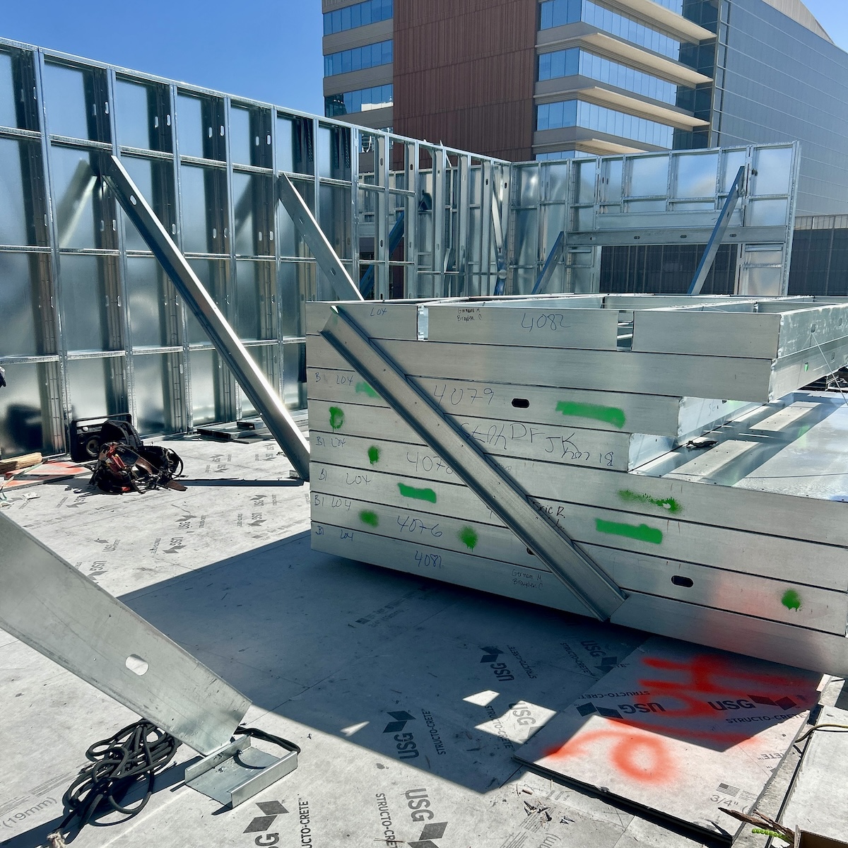
Crews framed the 7-story West Point II apartment building in just 75 days using prefabricated cold-formed steel (CFS) panels. The approach cut roughly 3 months from the overall construction schedule. Photo courtesy of Industrialized Construction Solutions
2. Coordinate Walls, Floors and Connections
Load-bearing walls cannot function independently of the floors they support. Engineers must design these components as an integrated structural system.
Key engineering considerations include:
- Gravity loads: Floor joists transfer loads to bearing walls
- Lateral forces: Diaphragms distribute lateral loads, while connections maintain structural continuity
- Longer spans: Engineers must evaluate strength, deflection and vibration while coordinating framing with architectural layouts and building services
The 8-story Element Hotel in Richmond, Virginia, demonstrates this integrated approach. The 110,000-square-foot hotel used load-bearing CFS walls and floor joists as its primary structural framing package.
US Frame Factory manufactured the components using technology from SFIA member Scottsdale Construction Systems.
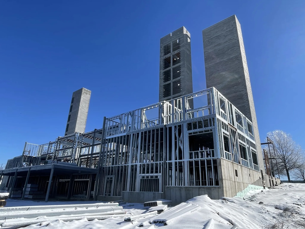
The 110,000-square-foot, 8-story Element Hotel in Richmond, Virginia, used load-bearing cold-formed steel (CFS) wall framing and floor joist systems as its primary structural package. Photo courtesy of Scottsdale Construction Systems
The Element Hotel incorporated several notable engineering features:
- Floor spans: CFS joists accommodated room spans of 15 to 20 feet
- Wall framing: Engineers specified 24-inch-on-center CFS framing throughout guest rooms and corridors
- Hybrid integration: On lower floors, engineers coordinated CFS framing with structural steel
- Wind resistance: Engineers designed the framing for a 112-mph basic wind speed
- Seismic design: The project met Seismic Design Category B and Site Class D requirements
These details demonstrate the coordination that taller CFS buildings demand. Engineers must resolve structural interfaces, connections and floor assemblies before fabrication begins.
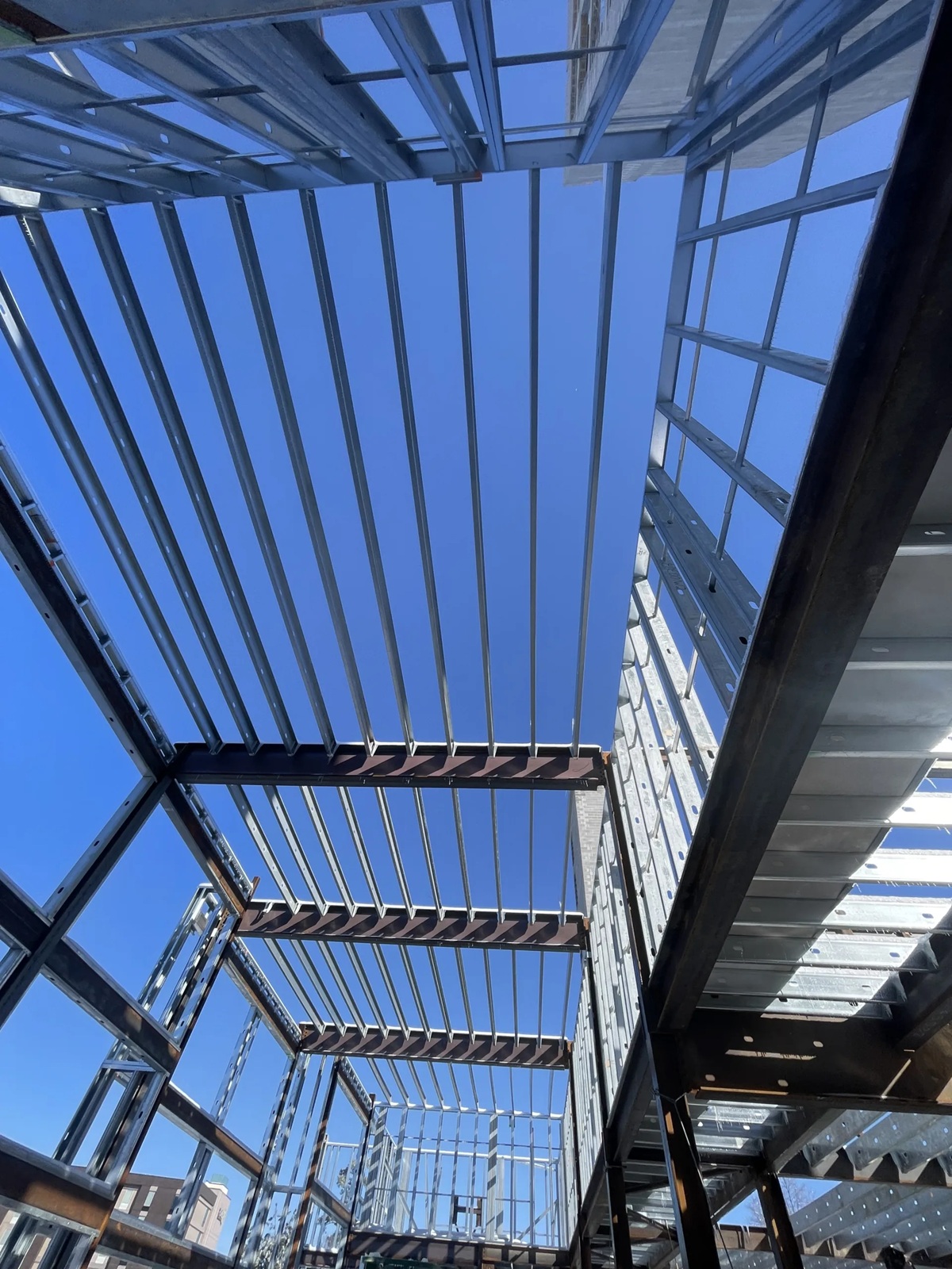
Load-bearing cold-formed steel (CFS) framing integrated with structural steel on the lower floors to create a coordinated structural system at the Element Hotel. Photo courtesy of Scottsdale Construction Systems
3. Address Seismic Performance and Height Limits
As buildings rise, lateral-force resistance becomes increasingly important. Engineers must address several critical challenges:
- Wind and seismic loads: Taller buildings place greater demands on shear walls, diaphragms, connections and anchorage systems
- Building drift: Excessive movement can damage structural and nonstructural components, even when the building remains stable
- Code limitations: In high-seismic regions, current provisions limit certain CFS lateral-force-resisting systems to 65 feet
The 65-foot restriction does not establish a universal height limit for CFS buildings. Engineers have already constructed CFS buildings reaching 10 stories and higher using appropriate structural systems.
However, researchers have now investigated whether CFS systems can safely exceed existing seismic design limits. Their findings could help expand future applications of load-bearing CFS framing.
A 10-Story Building Faces 18 Earthquakes
At the University of California San Diego, researchers constructed a full-scale, 10-story CFS test building known as CFS10. CFS10 is the capstone project within the larger Cold-Formed Steel—Natural Hazards Engineering Research Infrastructure (CFS-NHERI) research program.
The approximately 100-foot-tall CFS10 structure incorporated several structural features:
- Shear walls: Steel-sheet-sheathed walls resisted lateral forces
- Floor diaphragms: Dry floor diaphragms transferred lateral forces
- Lateral systems: Continuous tie rods resisted forces in one direction, while HSS chord studs and hold-down assemblies served the other
The research team installed more than 1,000 sensors throughout the building. Those instruments monitored structural movement, wall behavior, diaphragm performance and nonstructural systems.
Results Show CFS’s Seismic Resilience
Researchers conducted 18 earthquake simulations, including two Maximum Considered Earthquake motions. The building demonstrated strong seismic performance:
- Design-level earthquake: Peak interstory drift remained below approximately 0.5%
- Maximum recorded drift: Drift ratios reached approximately 1.2% during testing
- Structural condition: The building remained plumb, with no major structural distress observed
Researchers documented localized damage to finishes and wall interfaces. Independent assessors estimated less than $150,000 in repairs following the two Maximum Considered Earthquake motions.
Researchers continue analyzing the results to improve numerical models and support future standards development.
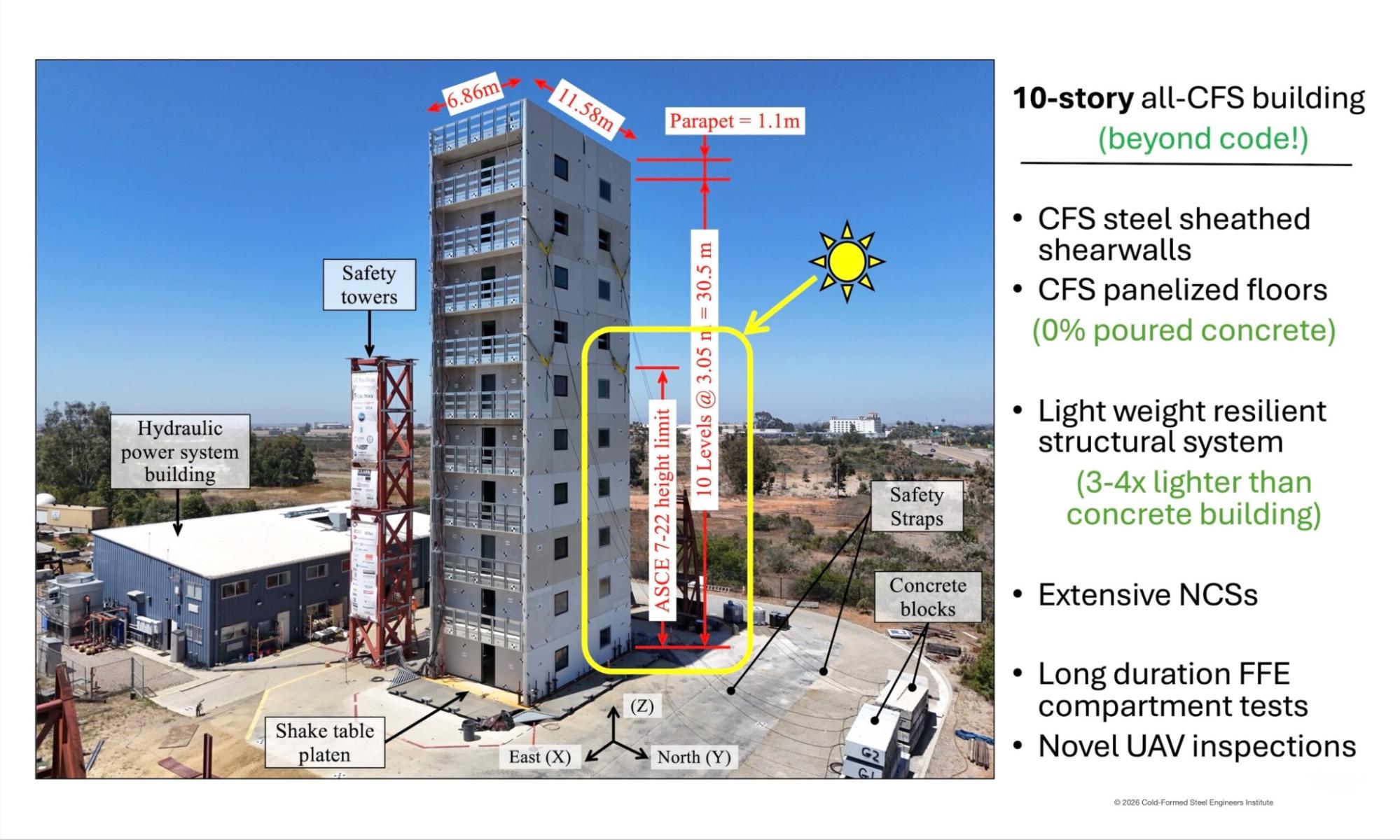
The 10-story CFS10 test building at UC San Diego exceeded current code seismic height limits and served as the centerpiece of extensive research. Copyright 2026 Cold-Formed Steel Engineers Institute (CFSEI). Used with permission.
4. Evaluate Fire Resistance and Floor Systems
Structural capacity alone does not determine a building’s allowable height. Construction classifications, occupancy requirements and fire-resistance ratings also influence the design.
CFS framing offers an important characteristic: Steel is noncombustible. However, engineers must evaluate complete wall and floor assemblies to establish the required fire resistance.
Floor-system selection also influences building weight, construction sequencing and coordination among trades. Two projects illustrate how engineers addressed these considerations:
- Two-hour fire-rated floor assembly: At the Element Hotel, engineers incorporated load-bearing CFS joists into a tested two-hour fire-rated floor and ceiling assembly. The system required no concrete topping slab.
- Lightweight CFS joists: At the West Point II Apartments, engineers replaced the specified concrete-filled metal deck with a lightweight CFS joist floor system. The revised system maintained acoustic and fire-performance requirements while eliminating separate concrete floor pours.
At West Point II, the revised floor system also helped consolidate framing work under one subcontractor. This simplified trade coordination and construction sequencing.
The lesson extends beyond selecting a fire-rated assembly. Engineers should evaluate structural performance, floor construction and code requirements together during early design.
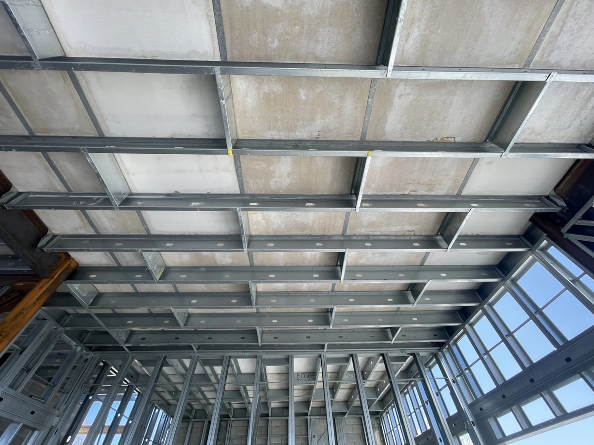
The tested two-hour fire-rated floor assembly at the Element Hotel integrated load-bearing cold-formed steel (CFS) joists without requiring a concrete topping slab. Photo courtesy of Scottsdale Construction Systems
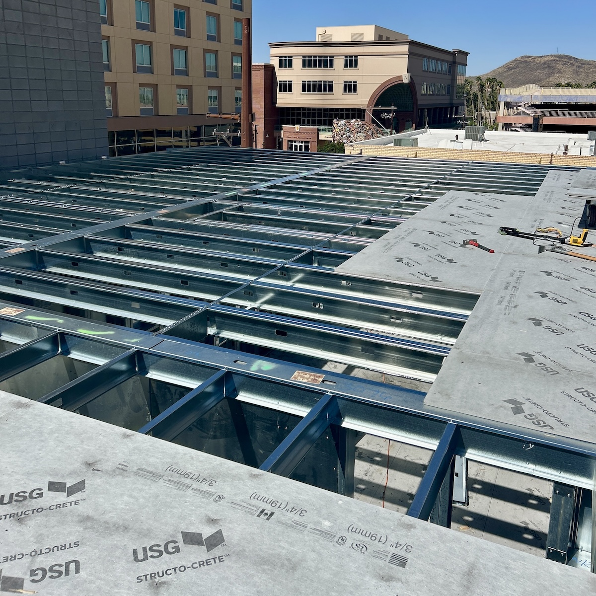
Cold-formed steel (CFS) floor joists and noncombustible magnesium oxide (MgO) structural panels helped West Point II’s owner reduce insurance costs compared with wood construction. Photo courtesy of Industrialized Construction Solutions
5. Plan Prefabrication Before Construction
Tall CFS construction requires precise coordination across multiple floors. Fabrication methods, installation sequencing and job-site constraints can influence the project’s schedule and cost.
Prefabrication can help teams manage those demands. Factory-produced components offer consistent dimensions and reduce the amount of framing work crews must complete on-site.
However, effective prefabrication starts with engineering decisions, not manufacturing equipment.
West Point II illustrates that connection. Its downtown Tucson site offered limited space for staging materials and equipment. The project team adopted several prefabrication strategies:
- Panelized framing: Crews assembled prefabricated CFS wall panels to accelerate construction
- Reduced crane time: The team shipped panels without sheathing to reduce weight and minimize lifting demands
- Digital fabrication: Custom software transferred engineering data from Revit models into shop drawings and roll-forming files
The project used 251 tons of CFS framing across 77,000 square feet. Crews erected the 7-story structure in just 75 days. According to the project team, the CFS framing process saved roughly two to three days per floor.
The Element Hotel succeeded due to substantial advance coordination. Its project timeline included:
- Planning: One year of preparation before fabrication
- Manufacturing: Approximately eight months producing framing components
- Installation: A 12-person crew erected the structural framing package
These projects demonstrate the relationship between design coordination and construction efficiency. Project teams can simplify field installation by resolving component details and sequencing before production.
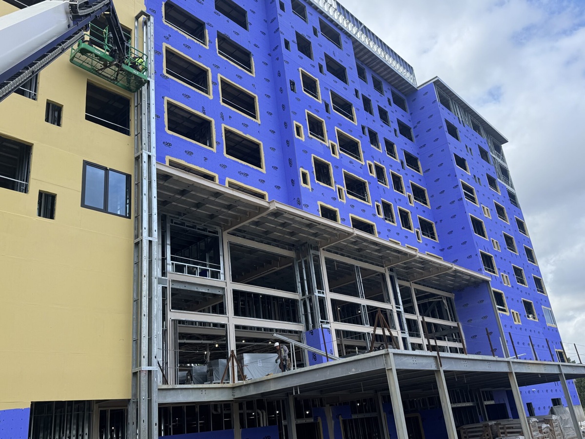
At the Element Hotel, extensive advance planning and eight months of prefabrication streamlined installation of the cold-formed steel framing by a 12-person crew.
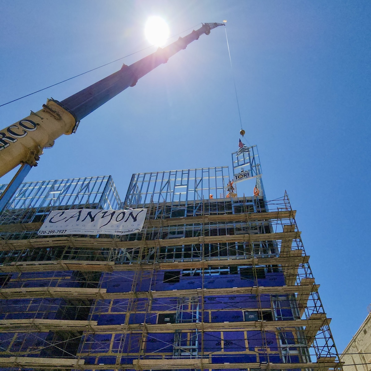
At West Point II Apartments, crews used cranes to lift prefabricated cold-formed steel (CFS) wall panels shipped without sheathing to reduce weight and crane time. Photo courtesy of Industrialized Construction Solutions
Where Should Project Teams Begin?
These projects offer a practical framework for evaluating taller load-bearing CFS buildings. Architects, engineers, fabricators and contractors should establish the structural strategy early in design.
Start with structural feasibility. Engineers should evaluate bearing-wall alignment, floor spans, gravity loads and lateral-force-resisting systems.
Establish code requirements. Construction type, occupancy, fire resistance and seismic provisions can influence building height and structural configuration.
Plan for fabrication. Coordinating component dimensions, connections and installation sequences early can help teams avoid costly field changes.
[gray box]
The BuildSteel™ CFS 101 Guide
The BuildSteel™ CFS 101 In Practice Guide highlights the value of this approach. Its project examples show how coordinated CFS design can …
- Reduce structural weight
- Improve tolerances
- Support efficient construction
Early collaboration also helps teams identify where CFS offers advantages over conventional framing systems. Those advantages depend on project requirements, structural layouts and construction methods.
[end gray box]
Cold-Formed Steel Framing 101
Building Taller: What’s Next for CFS?
The engineering evidence continues to grow. Seven- and eight-story projects demonstrate the practical applications of load-bearing CFS framing in mid-rise construction.
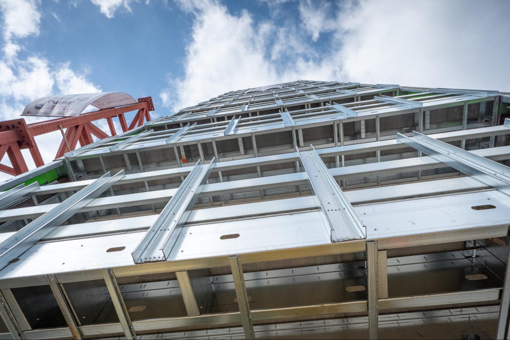
Advances in engineering and seismic research could expand opportunities for taller load-bearing cold-formed steel (CFS) buildings, pushing structural design beyond current limits.
West Point II shows how efficient structural layouts can eliminate costly transfer systems. The Element Hotel demonstrates the importance of coordinating walls, floors and structural connections.
The CFS10 research adds another dimension. Its seismic results could inform future structural systems and design standards for taller CFS buildings.
Yet the most important decisions still occur before construction begins. Project teams must evaluate loads, code requirements, structural configurations and construction strategies together.
Building taller with CFS is not simply about adding stories. It requires designing the entire building around a coordinated structural system.
As engineering methods advance, that approach could expand opportunities for load-bearing CFS framing in taller buildings.
Additional Resources
- CFS 101 in Practice: Real-World Examples of Project Teams Using Cold-Formed Steel
- Cold-Formed Steel Framing Passes 10-Story Earthquake Challenge
- Advancing Cold-Formed Steel in Mid-Rise Buildings
- Prefabricated Cold-Formed Steel Panels Cut Costs, Speed Construction of 7-Story Tucson Apartments
- Scottsdale Case Study: Cold-Formed Steel Framing Advances Mid-Rise Hotel Construction