
Excel Engineering received Second Place in the 2026 CFSEI Creative Detail Awards. The award recognized the company’s cold-formed steel (CFS) detail for Rutter’s No. 82 in Altoona, Pennsylvania.
The single-story building measures 100 by 100 feet. Excel Engineering designed its exterior CFS as non-load-bearing infill framing between the foundation and structural steel roof framing.
The project required the framing to accommodate vertical movement while transferring shear forces into plywood shear walls.
Images Courtesy of Excel Engineering, Inc.
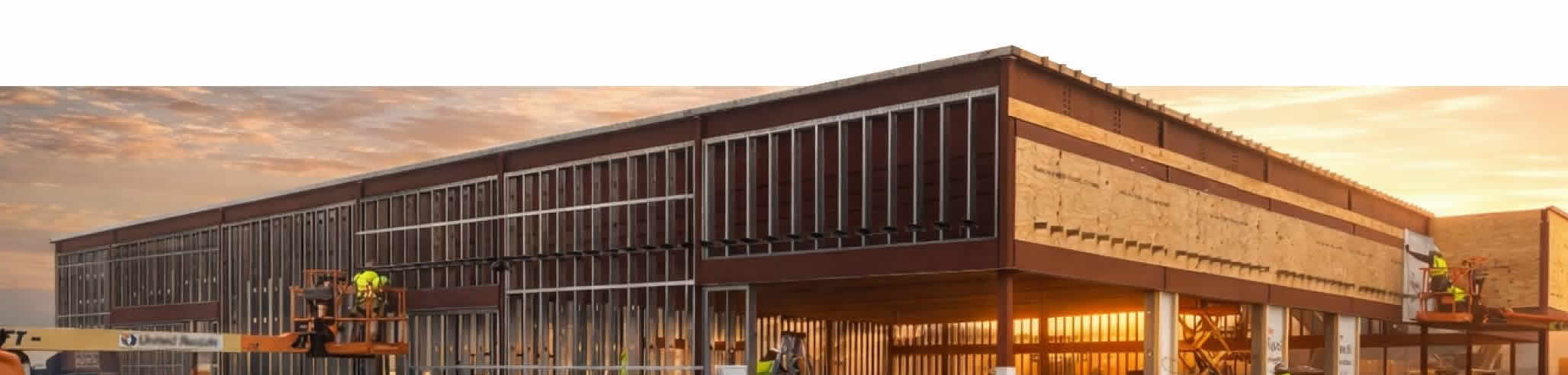
Excel Engineering designed the non-bearing cold-formed steel (CFS) infill framing for Rutter’s No. 82 in Altoona, Pennsylvania, including shear wall details that accommodated structural movement.
Balancing Movement and Shear Transfer
Structural steel beams spaced 5 feet on center formed the roof structure. Perimeter steel beams and columns supported the roof framing. The CFS infill framing rested on the foundation and connected beneath the perimeter beams with slip connections (SNIP A).
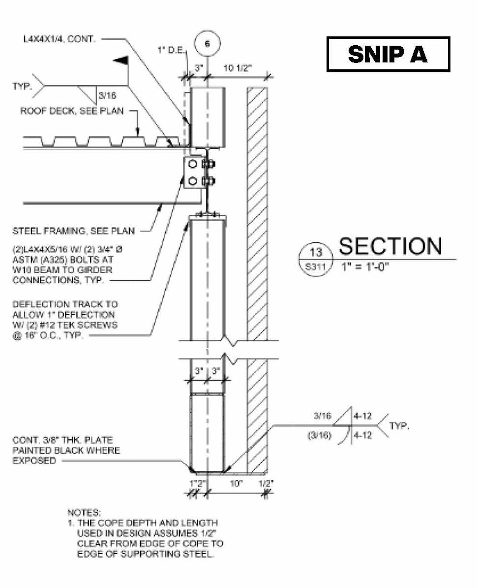
Non-load-bearing cold-formed steel (CFS) infill framing sits on the foundation and connects beneath perimeter structural steel beams with slip connections that accommodate vertical movement.
Structural plans identified plywood shear walls on three building sides (SNIP B). Moment frames provided lateral resistance along the fourth side. Moment frames provided lateral resistance along the fourth side. This arrangement created a critical detailing challenge. The wall needed to accommodate live load deflection while maintaining a clear shear load path.
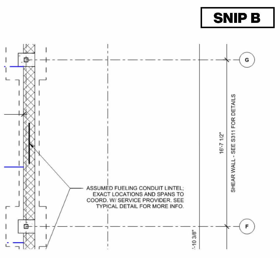
Plywood shear walls on three building sides required detailing that accommodated live load deflection while maintaining a clear shear load path.
Creating the Shear Load Path
Excel Engineering developed a wide-flange stud to collect shear forces at the top of the wall. The collector nested flat inside the slotted slip track.
Slots spaced 1 inch on center provided flexibility for screw placement. The connection transferred shear from the structural steel beam through the slotted track.
Loads then traveled into the wide-flange collector, top track and plywood sheathing. The resulting load path followed this sequence:
Steel beam → slotted slip track → wide-flange collector → top track → plywood sheathing
The detail allowed the wall to resist shear and out-of-plane wind loads while accommodating live load deflection.
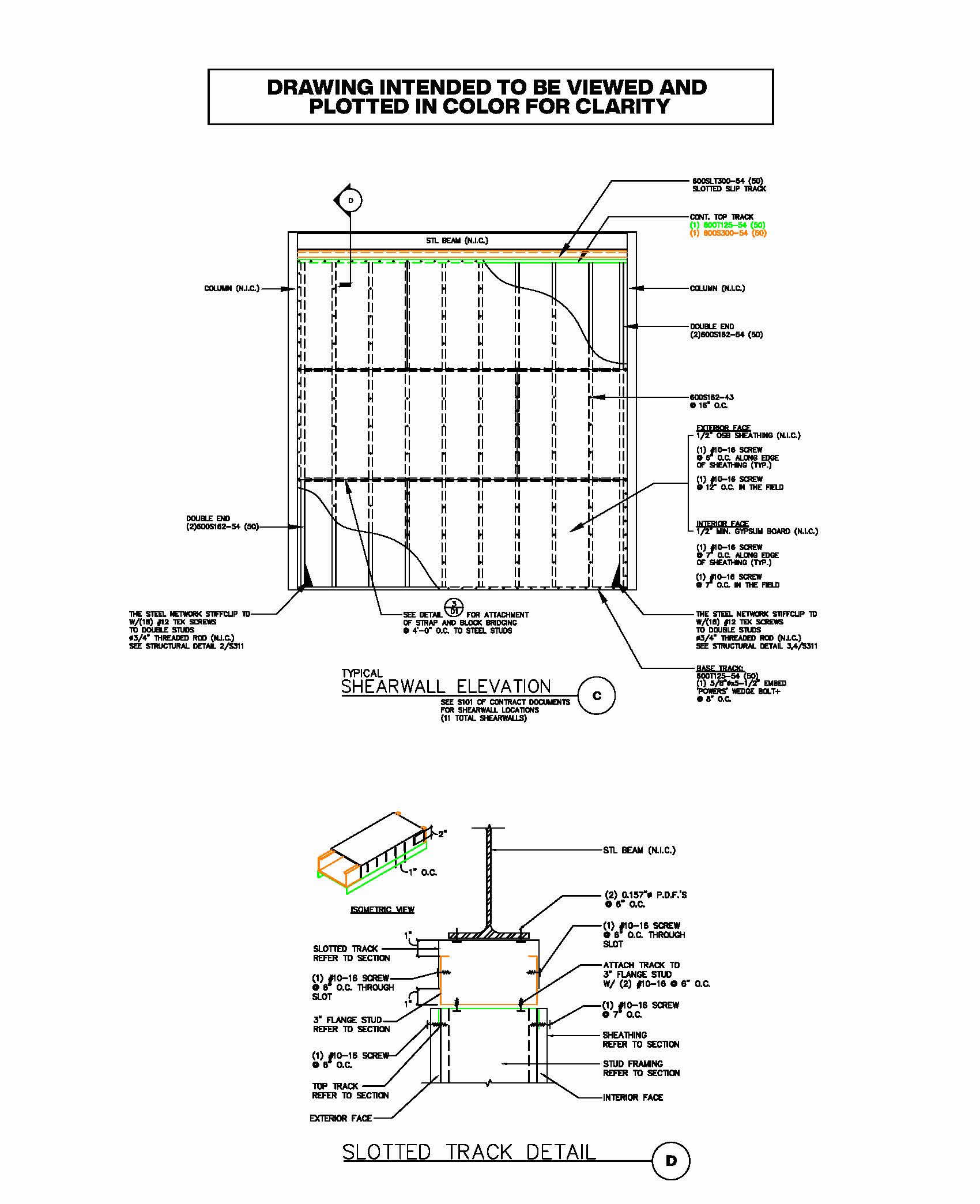
A wide-flange collector nested inside the slotted slip track transferred shear from the structural steel beam into the top track and plywood sheathing.
Verifying the Shear Wall Application
A later CFSEI seminar on non-bearing shear walls prompted Excel Engineering to review the completed detail. The guidance emphasized maintaining a clear load path and limiting these systems to appropriate applications.
Rutter’s No. 82 met the conditions discussed during the seminar. The building has 1-story and falls within Seismic Design Category A.
At least half the wall length on three sides also functioned as shear walls. This configuration kept the lateral forces manageable.
Excel Engineering’s review confirmed that the detail provided the required load path while accommodating structural movement.
Preserving the Load Path
The review also highlighted the importance of protecting non-bearing shear wall systems during future renovations.
Excel Engineering recommends identifying the shear wall framing so future work does not inadvertently remove critical components. The company also plans to note non-bearing shear wall systems in future submittals.
These measures helped preserve the intended load path after the original construction.
Resolving Competing Structural Requirements
Excel Engineering’s detail reconciled 2 competing requirements within a non-bearing CFS wall. The connection accommodated live-load deflection while maintaining shear transfer into the plywood.
The nested wide-flange collector and slotted slip track created a defined load path through the wall assembly.
That detail addressed structural movement, lateral loading and constructability within an application suited to non-bearing shear wall framing.
Read the full case study from CFSEI.
Rutters No. 82 in Altoona, Pennsylvania
Second Place – 2026 CFSEI Creative Detail Award
Winner: Excel Engineering
Daniel Church, Excel Engineering, Inc. Accepts Creative Detail Award, Second Place on Behalf of Joe Wilkum, Excel Engineering, Inc. Presented by Tammy Gleed, P.E., CFSEI Immediate Past Chair
Project
Rutters No. 82
432 Sabbath Rest Road
Altoona, PA 16601Completion Date
2024People
Owner
Rutter’sArchitect of Record
Mula GroupEngineer of Record for Structural Work
Onyx Design & ConsultingCold-Formed Steel Specialty Engineer
Joe Wilkum, Excel Engineering, Inc.Cold-Formed Steel Specialty Contractor
Dave Dillen, Lawruk Builders, Inc.

Additional Resources
- Excel Engineering Wins 2025 CFSEI Award for 10-Story CFS Project in Washington, D.C.
- Excel Engineering Wins Top 2025 CFSEI Creative Detail Award for Harrah’s in New Orleans
- Excel Engineering Wins 2024 CFSEI Award for Flexjet HQ’s Exterior and Interior CFS Framing