Each month, the Cold-Formed Steel Engineers Institute (CFSEI) publishes answers to questions about the design of cold-formed steel (CFS) framing. CFSEi experts receive questions through the 1-800-79STEEL hotline. Here’s a recent CFSEI question and answer about point load maximum for a hanger rod.
CFSEI Hotline: 1-800-79STEEL
Hanger Rod — Point Load Maximum
 Question
What technical document provides the maximum allowable point load for a hanger rod attached to the flange of a roof framing joist?
Here’s the actual question submitted: “I have a hanger rod attached to the flange of a roof framing joist. Where can I find the maximum point load for such conditions?”
 Answer
The connection design should consider the possible limit states of pull-over, pull-out and tension failure of the connector. These potential limit states are addressed by AISI S100.
The flange bending, however, requires engineering judgment. The bending of the flange theoretically may be evaluated using yield line theory. In the absence of a rigorous yield line evaluation, designers can employ a method based on the cantilever beam analogy.
Method No. 1
This method has been used in the metal building industry for hanging loads off of a purlin flange. The allowable load determined by using the cantilever beam analogy (Fig. 1) assumes elastic behavior as follows:
Mn = SxFy = (bt2 /6) Fy
M = Pn e
Pn = (bt2 /6e) Fy
P = Pn/Ω
where e = distance from load application to the web centerline, b = 2e, Fy = yield stress, t = base steel thickness and Ω = 2.0 (AISI S100, Section A1.2)
However, one could assume the development of the plastic moment, thus using the plastic section modulus in lieu of the elastic modulus. Therefore, when using the plastic section modulus, Sx = bt2/4.
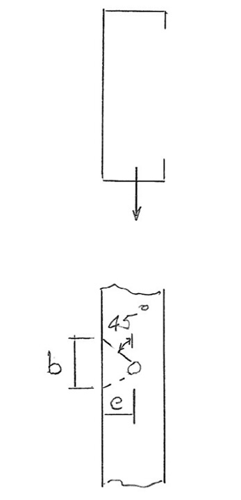
Fig. 1 — Using the cantilever beam analogy.
Method No. 2
The provisions of AISI S240, Section B3.2.5.2.2, Deflection Track Connection for C-Section Studs, are based on a cantilever beam analogy. Thus, one may consider using Eq. B3.2.5.2.-1 (Fig. 2) to determine the load capacity of the flange.
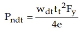
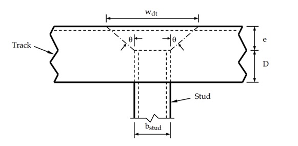
Fig. 2 — Eq. B3.2.5.2-1 of AISI S240 Section B3.2.5.2.2 may be used to determine the load capacity of the flange.
1.800.79STEEL
If you have any cold-formed steel (CFS) questions, contact CFSEI experts online or call CFSEI Hotline at 1.800.79STEEL.
Read more CFSEI “FAQ of the Month” questions and answers here:
CFSEI Hotline: 1-800-79STEEL

Cold-Formed Steel Engineers Institute
The Cold-Formed Steel Engineers Institute (CFSEI) comprises hundreds of structural engineers and other design professionals. Together, they are finding a better way to produce safe and efficient cold-formed steel (CFS) designs for commercial and residential structures. CFSEI members develop industry standards and design methods. CFSEI issues technical bulletins, organizes seminars and provides online training so that engineers and design professionals can improve their knowledge and skills. CFSEI is part of the Steel Framing Industry Association (SFIA) family. For more information, visit www.cfsei.org.
Additional Resources
- FAQ: Does Verbiage about Shear Walls and Strap-Braced Walls Removed from S400-20 Still Apply?
- FAQ: Does Limitation 2 of AISI S220, Section A1.2.1, Conflict with Limitation 3?
- SFIA Releases Updated Technical Guide with the Most Up-to-Date CFS Load and Span Tables in the Industry